
DIY: QuadClock PCB
Like most electronics tinkerers, I've built my share of clock projects. They're perfect for experimenting - simple enough to start, but with room to get properly creative. After finishing the QuadClock Orbix, it hit me: the circuit board I'd developed could help others skip the tedious electronics work and jump straight to the fun part.
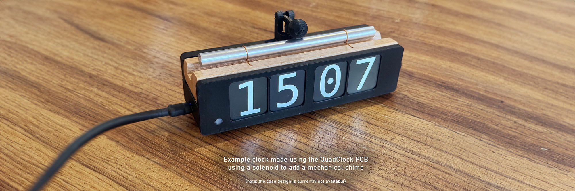
This PCB is essentially the brains of my finished clocks, ready for you to make it your own. It handles all the core functionality - driving the four displays, keeping precise time, and managing power - so you can focus on what matters: designing a unique case using your tools of choice. Use a 3D printer, a laser cutter, handcrafted woodwork, or even ceramics: let your creativity run wild. Want to incorporate a mechanical chime, a pendulum, or even a cuckoo? I’m excited to see what kinds of creations you’ll come up with!
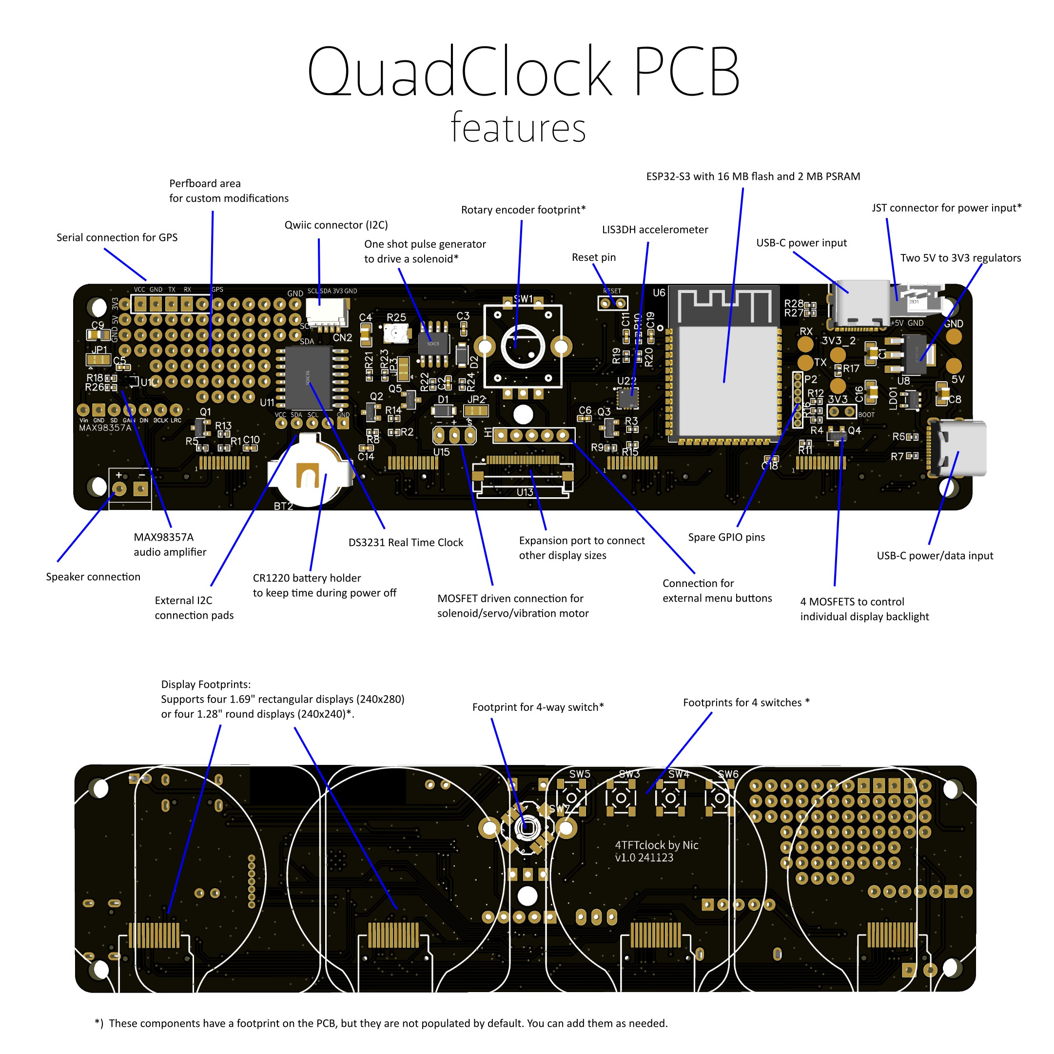
Features
The QuadClock PCB packs a ton of functionality onto a small PCB. Here’s what it offers
- ESP32-S3, equipped with 16 MB flash and 2 MB PSRAM for powerful performance.
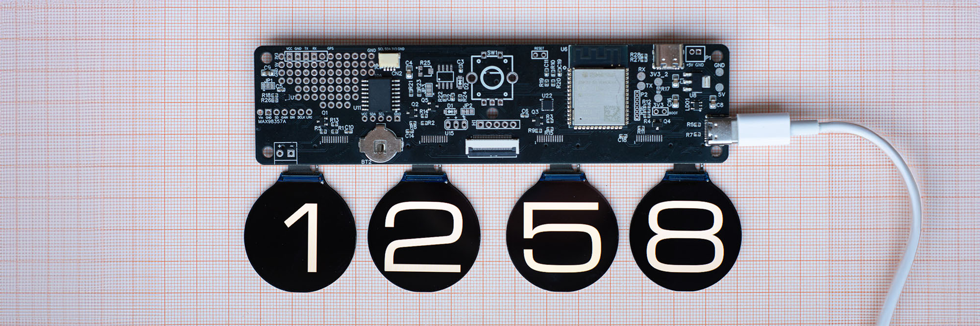
- Supports mounting of four 1.69" rectangular TFT displays (240x280) or four 1.28" round displays (240x240).
- Independent brightness control for each display, driven by four MOSFETs.
- Dual USB-C ports: One for power and firmware updates, the other dedicated to power only—use whichever fits your design best.
- DS3231 Real-Time Clock, using a highly accurate, temperature-compensated crystal oscillator with backup battery support (CR1220 battery not included).
- MAX98357 audio amplifier: Delivers 3W output for clock alarms or sound effects.
- LIS3DH accelerometer: Detects orientation, motion, and taps for interactive functionality.
- MOSFET driver: Ready to drive a solenoid, small servo, or vibration motor.
- NE555 safety circuit footprint: An optional hardware one-shot trigger to protect against solenoid overheating. Components can be added as needed.
- Rotary encoder and buttons: Includes footprints for a rotary encoder or up/down/enter/back buttons, plus header connections for placement flexibility.
- GPS module header: Adds optional GPS support for precision time synchronization.
- Breadboard space: Provides some room for custom experiments and add-ons.
- Qwiic I2C Connector: Simplifies adding I2C sensors or peripherals.
- Flat cable expansion connector: SPI, I2C, power, and control signals for alternative displays or custom modules (sharing lines with on-board connections).
The software is ready to run, and fully open source, so you can tweak it however you like. Got a great new feature? Submit a pull request on the GitHub repository, and I’d be happy to add it!
You can optionally order the 1.69" or 1.28" displays in sets of four, either unmounted or pre-mounted. If you choose the mounted option, I'll flash the firmware and make sure everything is fully tested.
In short, the QuadClock PCB is a powerful ESP32-S3 platform built for four-TFT-display clocks. With its real-time clock, accelerometer, audio amplifier, and extensive expansion options, it’s a flexible base for all kinds of clock projects.
Important to know
While the PCB simplifies creating your clock, it’s not entirely beginner-friendly. The TFT displays, if not ordered pre-mounted, require soldering a 12-pin flat cable directly to the PCB. The documentation offers some tips on how to mount them, but you’ll need patience and precise work to get it right. To help with this process, the documentation page includes 3D design files for printing a jig that holds the displays in the correct position during soldering, which helps a lot aligning them.
When ordering, you will get the PCB with all components mounted, but it is shipped without displays (unless you add them to your order), and without case, accessoires, batteries, switches, external connectors, etc., as those are highly dependant on your clock design. As a minimum, you will need 4 TFT displays and a rotary encoder. Links to compatible displays and useful extra components are provided on the documentation pages. As noted, you'll have to come up with a case design. I don't have any design files for cases available.
Lastly, I want to mention that I’m just a hobbyist sharing something I’ve put a lot of time and effort into. This isn’t a polished commercial product, but a project made with passion. I do my best to make everything as good as possible, and I hope it brings you some fun while tinkering!